 Solid design, long life Multi Level Switch is best suited for most level control applications. Our level controls are used in co-generation to water distillers. Ideal for simple high / low level control or complicated procedures requiring pump or solenoid control with high low alarms plus backup pump control. Solid design, long life Multi Level Switch is best suited for most level control applications. Our level controls are used in co-generation to water distillers. Ideal for simple high / low level control or complicated procedures requiring pump or solenoid control with high low alarms plus backup pump control.
Custom level probes can accommodate from one to seven switch stations with customer requested states. (normally open or normally closed) Process connection can be - well pretty well what do you need - sanitary - NPT
-nothing - ANSI flange - custom flange - 90 deg. etc.
Material - most options including titanium, stainlesssteel, brass, Teflon (TM), etc. See PVC in another section.
The level switch is easy order and lead time is usually excellent. Most float and connection sizes available.
If a particular option is not shown in the spec sheet - please request it.
We cannot show every possible design - as many haven't been thought of yet.
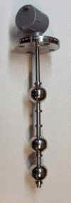
How Does It Work?
Hermitically sealed read switches set up on a custom wiring harness per customer requirements including activation points and switch state. The switch state can be field adjusted but the position of the switch cannot be moved once set. Factory repair or adjustment is the only option. All measurements are
from below the process connection (per spec sheet below) and states ( open or closed are in the dry position.)
Switch points are activated by magnet equipped float's) as the process level rises or falls either opening or closing the switch. This is a simple but very cost effective and reliable design for level control and level indication.
See other pages on how control is accomplished.
 Click here Part Numbers in pdf.
Click - Stainless Steel Assembly Part Numbers - Web Format
Brass Probe Assembly Part Numbers - Web Format
How to Build a Part Number for a Multi Level Probe
|
Material
|
Pressure
|
Temperature
|
Specific
Gravity
|
|
| 316 Stainless Steel |
750 psi |
-040 to 300 deg F |
0.75 |
Other Sp.Gr Available |
| PVC |
100 psi |
- 10 to 140 deg. F |
0.6 |
|
| Kynar |
100 psi |
-10 to 240 F |
0.6 |
|
| Polypropylene |
100 psi |
100 deg. F |
0.7 |
|
| Buna Material |
200 |
-40 to 225 F OIl |
0.55 |
Other Sp.Gr Available |
|
|
Stainless
Fittings Size
|
2"
Stainless
Float
|
1 1/2"
Stainless
Float
|
1 1/2"
Stainless
Pancake Float
|
1 9/16"
Buna
Float
|
1 1/4"
Buna
Float
|
1 7/8"
PVC
Float
|
2"
SS
Interface
|
2"
Titanium
Float
|
| Flange ( X ) |
SR x F - 1 |
SR x F - 2 |
SR x F - 7 |
SR x 3 |
SR x - 4 |
SR x F - 5 |
SR x F - 6 |
SR x F - 8 |
| 2" NPT |
SR20 - 1 |
SR20 - 2 |
SR20 - 7 |
SR20 - 3 |
SR20 - 4 |
SR20 - 5 |
SR20 - 6 |
SR20 - 8 |
| 1 1/2" NPT |
|
SR15 - 2 |
SR15 - 7 |
SR15 - 3 |
SR15 - 4 |
SR15 - 5 |
SR15 - 6 |
SR15 - 8 |
| 1 1/4" NPT |
|
|
|
|
SR14 - 4 |
|
|
|
| 3/4" NPT |
SR75 - 1 |
SR75 - 2 |
SR75 - 7 |
SR75 - 3 |
SR75 - 4 |
SR75 - 5 |
SR75 - 6 |
SR75 - 8 |
| 1/2" NPT |
SR50 - 1 |
SR50 - 2 |
SR50 - 7 |
SR50 - 3 |
SR50 - 4 |
SR50 - 5 |
SR50 - 6 |
SR50 - 8 |
| 3/8" NPT |
SR37 - 1 |
SR37 - 2 |
SR37 - 7 |
SR37 - 3 |
SR37 - 4 |
SR37 - 5 |
SR37 - 6 |
SR37 - 8 |
| 1/4" NPT |
SR25 - 1 |
SR25 - 2 |
SR25 - 7 |
SR25 - 3 |
SR25 - 4 |
SR25 - 5 |
SR25 - 6 |
SR25 - 8 |
| Tube End |
SR10 - 1 |
SR10 - 2 |
SR10 - 7 |
SR10 - 3 |
SR10 - 4 |
SR10 - 5 |
SR10 - 6 |
SR10 - 8 |
|
|
Brass
Fittings Size
|
2"
Stainless
Float
|
1 1/2"
Stainless
Float
|
1 1/2"
Stainless
Pancake Float
|
1 9/16"
Buna
Float
|
1 1/4"
Buna
Float
|
1 7/8"
PVC
Float
|
2"
SS
Interface
|
2"
Titanium
Float
|
| 2" NPT |
BR20 - 1 |
BR20 - 2 |
BR20 - 7 |
BR20 - 3 |
BR20 - 4 |
BR20 - 5 |
BR20 - 6 |
BR20 - 8 |
| 1 1/2" NPT |
|
BR15 - 2 |
BR15 - 7 |
BR15 - 3 |
BR15 - 4 |
BR15 - 5 |
BR15 - 6 |
BR15 - 8 |
| 1 1/4" NPT |
|
|
|
|
BR14 - 4 |
|
|
|
| 3/4" NPT |
BR75 - 1 |
BR75 - 2 |
BR75 - 7 |
BR75 - 3 |
BR75 - 4 |
BR75 - 5 |
BR75 - 6 |
BR75 - 8 |
| 1/2" NPT |
BR50 - 1 |
BR50 - 2 |
BR50 - 7 |
BR50 - 3 |
BR50 - 4 |
BR50 - 5 |
BR50 - 6 |
BR50 - 8 |
| 3/8" NPT |
BR37 - 1 |
BR37 - 2 |
BR37 - 7 |
BR37 - 3 |
BR37 - 4 |
BR37 - 5 |
BR37 - 6 |
BR37 - 8 |
| 1/4" NPT |
BR25 - 1 |
BR25 - 2 |
BR25 - 7 |
BR25 - 3 |
BR25 - 4 |
BR25 - 5 |
BR25 - 6 |
BR25 - 8 |
| Tube End |
BR10 - 1 |
BR10 - 2 |
BR10 - 7 |
BR10 - 3 |
BR10 - 4 |
BR10 - 5 |
BR10 - 6 |
BR10 - 8 |
1) Choose the process connection and then move across to the required float. eg. SR20 - 1 = 2" NPT with SS float
2) Determine switch points ( from 1 to 7) and then the level or switch point measured form below the thread and the state.
The state means normally open (N/O) or normally closed N/C in the dry position - no fluid in the tank.
N/O is indicated with a letter "A" switch closes on rise opens on fall
N/C is indicated with a letter "B" switch open on rise closes on fall
3) Choose unit of measure "C" indicates inches "D" indicates millimeters
Example
SR20 - 1 -10A - 15A - 20B - 25A - C = SS probe, 2" NPT, L1 = 10" N/O, L2 = 15"N/O, L3 = 20" N/C, L4 = 25" N/O
or
BR50 - 4 - 6A - 18A - 36B - D =
Brass probe, 1/2" NPT facing up, 1 1/4" buna floats, L1 = 6mm N/O, L2 = 18mm N/O , L3 = 36MM N/C
NOTE
1 9/16" and 1 /1/4" Floats are the same price
-
Minimum distance between switch points using one float making bottom N/C top N/O is 1/4" +/-
-
Minimum distance between switch points using a float for each station is 3"
-
2" of probe is required after the last level or point
-
New pancake floats allow closer distance
|